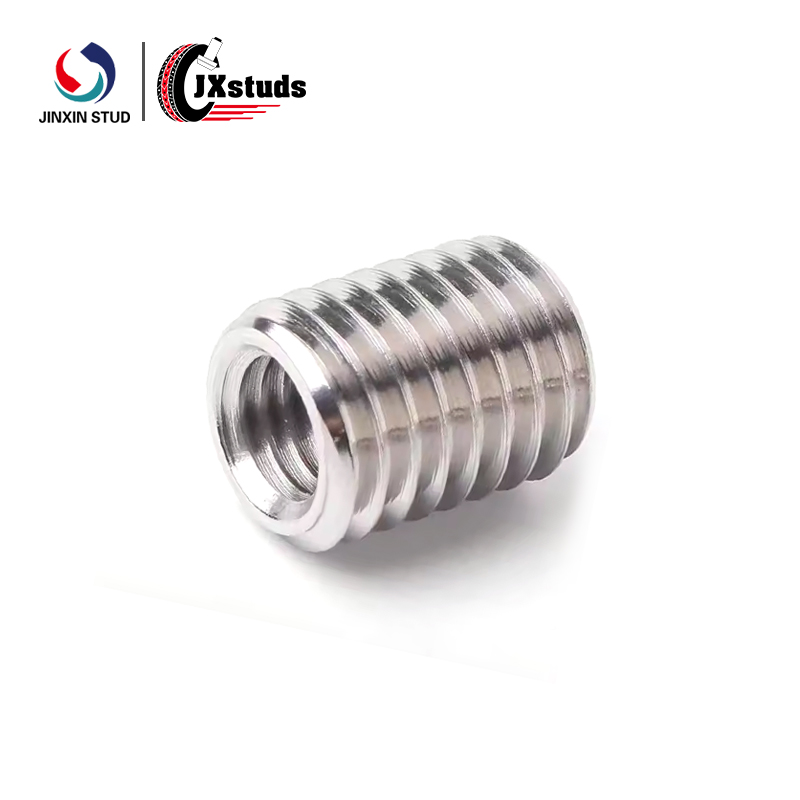
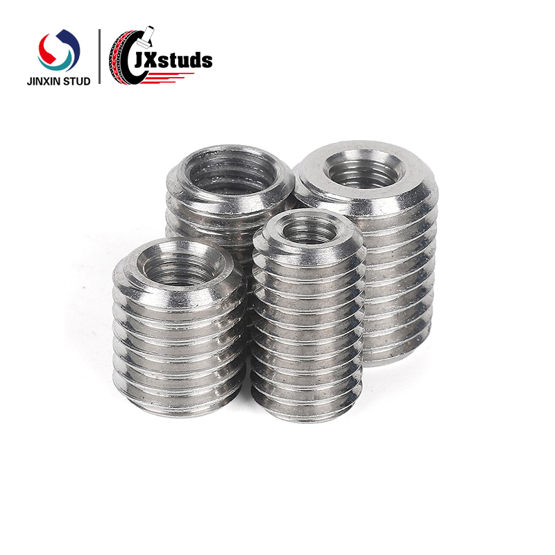
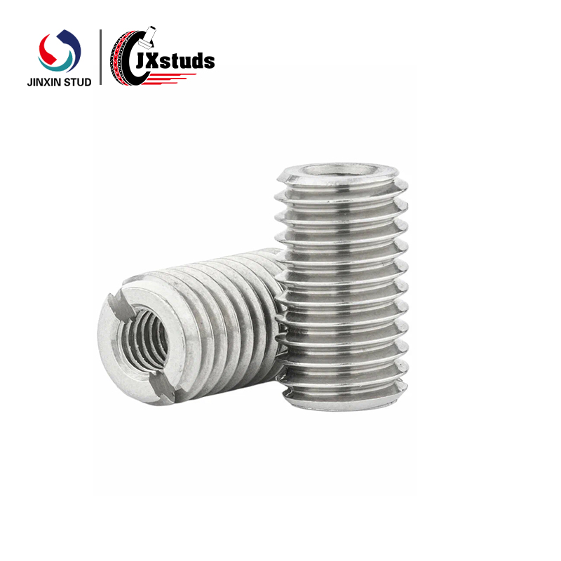
Design Overview: Integrated Male-Female Threading
A male-female threaded insert serves dual functions in a single component. The male (external) thread attaches to a chassis, panel, or mounting surface, while the female (internal) thread accepts a screw or bolt for component stacking, spacing, or secure fastening. This integrated design reduces part count, simplifies assembly, and maintains precise alignment between stacked components.
Key Design Features
| Feature | Function |
|---|---|
| External Thread (Male) | Mounts directly into tapped holes, nuts, or sheet metal; provides fixed attachment point |
| Internal Thread (Female) | Accepts mating screw or bolt; supports stacked assemblies or removable components |
| Body Holes | Enables secondary wiring, safety wire locking, or mechanical interlock |
| Slots / Cutouts | Allows positional adjustment, ventilation, or tool access |
| Hex or Knurled Body | Provides wrench flats for installation; prevents rotation during assembly |
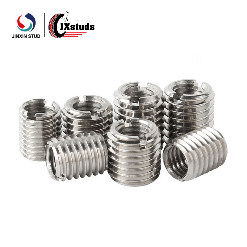
Hole & Slot Features
The distinguishing characteristic of these inserts is the integration of holes or slots into the body or flange:
Cross-Hole: Drilled through the body perpendicular to the axis—used for safety wire, cotter pins, or cable routing
Axial Slot: Cut along the body length—enables compression fit, positional adjustment, or serves as a locating keyway
Flange Holes: Mounting holes in an integrated flange—provides additional fastening points
Slotted Head: Screwdriver slot in the head—facilitates installation where wrench access is limited
Threading Options: Metric & Inch
We support full customization of thread specifications:
| Thread System | Standards | Typical Sizes |
|---|---|---|
| Metric | ISO 261 / DIN 13 | M3 – M12 (male), M2 – M10 (female) |
| Inch (UNC/UNF) | ASME B1.1 | #4 – 1/2″ (male), #2 – 3/8″ (female) |
| Special Pitches | Customer specification | Fine, extra-fine, or non-standard |
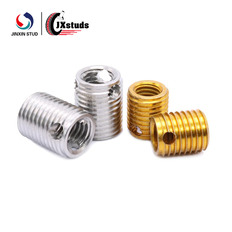
Material Selection
| Material | Properties | Typical Applications |
|---|---|---|
| Carbon Steel (Grade 10B21 / 12L14 / 10.9) | High strength, cost-effective, heat-treatable | Industrial equipment, heavy-duty assemblies |
| Stainless Steel (303 / 304 / 316) | Corrosion resistance, non-magnetic, good strength | Medical devices, marine, food equipment, outdoor applications |
Surface Finishes
| Finish | Carbon Steel | Stainless Steel |
|---|---|---|
| Zinc Plating | Standard (72–240 hrs salt spray) | Not applicable |
| Zinc-Nickel | High corrosion (500–1,000 hrs) | Not applicable |
| Black Oxide | Cosmetic, minimal dimensional change | Available (black passivation) |
| Passivation | Not applicable | Standard for stainless |
| Electropolishing | Not applicable | Enhanced corrosion resistance, bright finish |
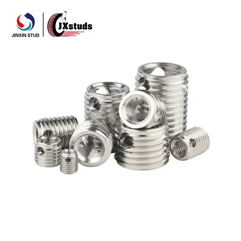
Custom Manufacturing Capabilities
We support full customization across geometry, threading, and features:
| Custom Parameter | Options |
|---|---|
| Overall Length | 5 mm – 60 mm |
| Body Shape | Round, hex, square, custom profile |
| External Thread Length | Partial or full-length threading |
| Internal Thread Depth | Blind or through-hole configuration |
| Hole/Slot Placement | End, side, flange, or multiple locations |
| Hole Diameter | 1 mm – 8 mm |
| Slot Width/Length | Customer specified |
| Flange Design | Integral flange with mounting holes |
| Parameter | Carbon Steel | Stainless Steel |
|---|---|---|
| Thread Sizes (Male) | M3 – M12, #4 – 1/2″ | M3 – M10, #4 – 3/8″ |
| Thread Sizes (Female) | M2 – M10, #2 – 3/8″ | M2 – M8, #2 – 5/16″ |
| Length Range | 5 – 60 mm | 5 – 50 mm |
| Body Diameter | 5 – 20 mm | 5 – 18 mm |
| Hole Diameter | 1 – 8 mm (custom) | 1 – 6 mm (custom) |
| Tensile Strength | 800 – 1,200 MPa (Grade 10.9) | 500 – 700 MPa (304) |
| Hardness | 25–38 HRC | 80–95 HRB |
| Corrosion Resistance | 72–1,000 hrs (finish dependent) | 500–1,000 hrs (passivated) |
| Thread Class | 6g (male), 6H (female) | 6g (male), 6H (female) |
| Custom Features | Cross-hole, slot, flange, knurl | Cross-hole, slot, flange, knurl |
| Application | Function |
|---|---|
| Stacked PCB Assemblies | Spacing and securing multiple circuit boards |
| Equipment Enclosures | Panel-to-panel mounting with serviceable access |
| Mechanical Linkages | Pivot points with integrated safety wire hole |
| Modular Frame Systems | Adjustable connections with slotted positioning |
| Electrical Bus Assemblies | Insulated standoffs with through-hole for wiring |
Thread Verification: Go/no-go gauging on both male and female threads
Dimensional Inspection: Critical features measured via optical comparator or CMM
Feature Verification: Hole position, slot dimensions, and geometry confirmed per drawing
Material Certification: Chemical and mechanical properties documented per batch
Lot Traceability: Complete manufacturing history maintained
| Step | Description |
|---|---|
| 1. Specification | Customer provides thread sizes, length, hole/slot details, material, finish |
| 2. Engineering Review | Feasibility assessment, drawing creation, tooling requirements identified |
| 3. Tooling Development | Customer-approved tooling cost; mold or machining setup completed |
| 4. Sample Production | 25–200 units produced for fitment and performance validation |
| 5. Qualification | Customer approves samples; production scheduling initiated |
| 6. Batch Manufacturing | Production runs from 1,000 to 500,000+ units |
| 7. Packaging & Delivery | Bulk cartons, custom kitting, or tape-and-reel as specified |
Minimum Order Quantities: Flexible based on complexity; sample quantities available for qualification


")


")
")


")


