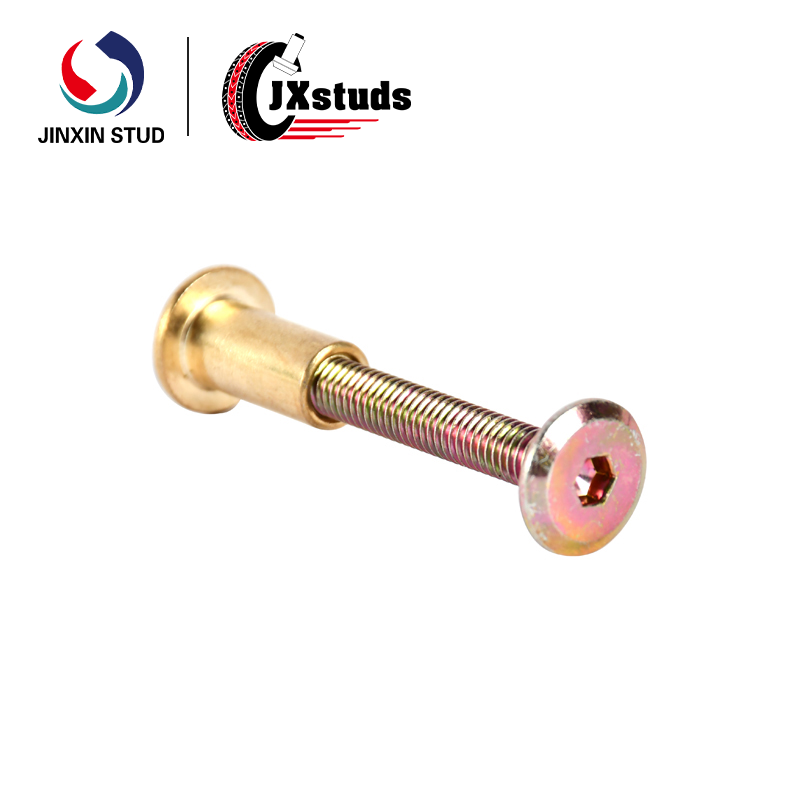
Product Architecture: Two-Piece Mechanical Interlock
The mating rivet screw system consists of two precision-engineered components that function as a unified fastening assembly:
| Component | Description |
|---|---|
| Female Socket (Mother Component) | A tubular, blind-ended receptacle with internal threads. Installs into the first workpiece via press-fit, clinching, or riveting. Features retention features (knurl, groove, or collar) to secure it within the host material. |
| Male Screw (Child Component) | A threaded stud with integral head. Passes through the second workpiece and engages into the female socket from the accessible side. Tightening draws the assembly together, creating a permanent clamped joint. |
Mechanical Principle
The system operates on a blind fastening principle:
| Stage | Action |
|---|---|
| 1. Female Installation | Female socket is installed into the first panel or component from the accessible side. Retention features lock it permanently in place. |
| 2. Workpiece Alignment | Second workpiece is positioned over the installed female socket. |
| 3. Male Insertion | Male screw is inserted through the second workpiece and threaded into the female socket. |
| 4. Torque Application | Tightening draws the male screw into the female socket, compressing both workpieces together. The female socket remains stationary due to its retention features, while the male screw advances to achieve specified clamp load. |
This configuration enables:
Single-Side Installation: No backside access required for either component
Blind Assembly: Ideal for hollow sections, closed profiles, and pre-assembled enclosures
Vibration Resistance: Positive mechanical lock resists loosening under dynamic loads
Serviceability: Can be disassembled and reassembled without damaging the host materials

Application Domains
| Industry | Application | Rationale |
|---|---|---|
| Automotive | Interior trim panels, door assemblies, plastic-to-metal fastening | Blind installation in closed sections; vibration resistance; serviceable for maintenance |
| Appliance Manufacturing | Sheet metal enclosures, housing assemblies, component mounting | High-volume production compatibility; consistent clamp load; corrosion resistance |
| Electronics Enclosures | Rack-mount equipment, server chassis, control panels | Space-constrained assemblies; no backside hardware; clean aesthetics |
| Furniture Manufacturing | Flat-pack assembly points, structural connections | Blind fastening in tubular frames; tool-less or simple tool assembly |
| Industrial Equipment | Guard panels, access covers, modular frame connections | Permanent yet serviceable fastening; corrosion protection |
Customization Parameters
| Parameter | Options |
|---|---|
| Thread Size | Metric M3 – M12; Inch #4 – 1/2″; custom pitches available |
| Overall Length (Assembled) | 6 mm – 50 mm (custom ranges) |
| Female Socket Length | 5 mm – 40 mm |
| Male Screw Length | 4 mm – 35 mm |
| Head Style (Male) | Hex flange, pan head, countersunk, truss, custom |
| Head Style (Female) | Flush, countersunk, hexagonal, round with knurl |
| Retention Features | Knurled body, hexagonal press-fit, groove, collar |
| Material | Carbon steel (8.8–12.9), stainless steel (304/316), aluminum, brass |
| Surface Finish | Zinc plating, zinc-nickel, Geomet, Dacromet, black oxide, passivation, anodize |
| Thread Locking | Pre-applied nylon patch, micro-encapsulated adhesive, or prevailing torque feature |
| Drive Type | Phillips, Pozidriv, Torx, hex socket, slotted, custom |
Material Selection Guide
| Material | Strength | Corrosion Resistance | Typical Applications |
|---|---|---|---|
| Carbon Steel (Grade 8.8) | 800–880 MPa | Moderate (finish dependent) | Cost-sensitive industrial, automotive interior |
| Carbon Steel (Grade 10.9) | 1,000–1,100 MPa | Moderate (finish dependent) | High-strength structural connections |
| Stainless Steel A2 (304) | 500–700 MPa | Good | Electronics, medical, general purpose |
| Stainless Steel A4 (316) | 500–700 MPa | Excellent | Marine, food processing, chemical exposure |
| Aluminum (6061) | 200–300 MPa | Good (anodized) | Lightweight assemblies, electronics |
| Parameter | M4 Set | M5 Set | M6 Set | #8-32 Set |
|---|---|---|---|---|
| Thread Size | M4 × 0.7 | M5 × 0.8 | M6 × 1.0 | #8-32 UNC |
| Female Socket Length | 8.0 mm | 10.0 mm | 12.0 mm | 9.5 mm |
| Female Socket OD | 6.0 mm | 7.5 mm | 9.0 mm | 0.280″ |
| Female Head Diameter | 7.0 mm | 8.5 mm | 10.0 mm | 0.330″ |
| Male Screw Length | 10.0 mm | 12.0 mm | 15.0 mm | 0.400″ |
| Male Head Diameter | 7.0 mm | 8.5 mm | 10.0 mm | 0.330″ |
| Assembled Grip Range | 3–6 mm | 4–8 mm | 5–10 mm | 3–7 mm |
| Recommended Torque | 2.5–3.5 N·m | 4.5–6.0 N·m | 7.0–9.0 N·m | 2.0–3.0 N·m |
| Installation Method | Press-fit / Clinch | Press-fit / Clinch | Press-fit / Clinch | Press-fit / Clinch |
| Parameter | Carbon Steel (10.9) | Stainless Steel (A2/A4) | Aluminum (6061) |
|---|---|---|---|
| Tensile Strength (MPa) | 1,000–1,100 | 500–700 | 200–300 |
| Shear Strength (kN, M6 set) | 12.5 | 8.0 | 3.5 |
| Proof Load (kN, M6 set) | 18.0 | 12.0 | 5.0 |
| Corrosion Resistance (Salt Spray) | 72–1,000 hrs (finish dependent) | 500–1,000 hrs (passivated) | 336+ hrs (anodized) |
| Operating Temperature | -40°C to +150°C | -40°C to +300°C | -40°C to +150°C |
| Magnetic | Yes | Non-magnetic | Non-magnetic |
| RoHS Compliant | With approved finishes | Yes | Yes |
| Process Aspect | Description |
|---|---|
| Primary Manufacturing | Cold heading (male screws); CNC turning or cold forming (female sockets) |
| Secondary Operations | Thread rolling, heat treatment, surface finishing, thread locking application |
| Inspection | 100% go/no-go thread gauging; dimensional sampling per AQL standards; optical sorting available for critical dimensions |
| Testing | Torque-tension validation; salt spray corrosion testing; push-out and pull-out verification per batch |
| Documentation | Material Test Reports (EN 10204 3.1); dimensional inspection reports; coating certifications; lot traceability |
| Certification | ISO 9001; IATF 16949 (automotive); PPAP Level 3 available |
| Parameter | Detail |
|---|---|
| Minimum Order Quantity | 100,000 sets (combined male + female components) |
| Retail Availability | None; wholesale / OEM distribution only |
| Custom Tooling | Customer-owned tooling; tooling development supported with amortization options |
| Sample Policy | Qualification samples available for testing; tooling fees apply for custom specifications |
| Lead Time | 4–8 weeks depending on complexity, material availability, and quantity |
| Packaging | Bulk cartons (1,000–5,000 sets per carton); custom kitting per assembly requirements; anti-corrosion packaging available |
| Shipping | Global export; FOB manufacturing facility or delivered pricing available |
| Step | Description |
|---|---|
| 1. Specification | Customer provides thread size, grip range, materials, finish, head styles, and any special requirements |
| 2. Engineering Review | Design feasibility assessment; CAD drawing creation; tooling requirements identified |
| 3. Tooling Development | Customer approves tooling costs; molds, dies, and forming tools manufactured (4–6 weeks) |
| 4. Sample Qualification | 200–500 sample sets produced; customer validates fit, function, and performance |
| 5. Production Release | Sample approval received; batch manufacturing initiated |
| 6. Supply Agreement | Long-term supply agreement established; scheduled deliveries aligned with production requirements |


")


")


")


