Mechanical Function: Articulation Meets Fastening
The universal ball head fastener serves a dual mechanical role that distinguishes it from conventional threaded fasteners. While a standard screw provides only clamping force along a single axis, the ball head design incorporates a spherical articulation surface that allows relative motion between connected components.
Linkage Method
The connection method operates on a ball-and-socket principle. The spherical head seats into a corresponding concave socket, rod end, or linkage housing, creating a joint that permits:
Angular Articulation: Rotation about multiple axes, typically up to 15–30 degrees from center
Rotational Freedom: Full 360-degree rotation within the socket
Load Transmission: Transfer of axial push-pull forces while accommodating misalignment
The threaded portion of the component provides the fixed attachment point to a structural element, chassis, or mounting bracket. This combination creates a mechanical link that can transmit force while allowing the connected components to move relative to one another—a fundamental requirement for any mechanism requiring controlled motion between two points.

Threaded vs. Press-Fit Configurations
We offer two primary configuration families to suit different assembly requirements:
| Configuration | Threaded Shank | Press-Fit / Stud Type |
|---|---|---|
| Connection Method | Threads into tapped hole or accepts nut | Presses into housing or retained by shoulder |
| Installation | Torque-controlled, removable | Permanent or semi-permanent installation |
| Adjustability | Allows fine positioning during assembly | Fixed position determined by housing |
| Typical Shank Features | Full thread or partial thread with shoulder | Grooved, knurled, or smooth shank for press-fit |
Articulation Characteristics
The spherical interface is defined by several critical parameters that determine joint behavior:
Articulation Angle: The maximum angular displacement from the neutral axis. Standard designs accommodate 15–25 degrees, with custom configurations available up to 40 degrees.
Articulation Torque: The resistance to motion within the socket. This can be engineered as low-friction for free movement or controlled-friction for position-holding applications.
Radial Play: The clearance between ball and socket. Tight tolerances (0.02–0.05 mm) provide precise positioning with minimal free play; looser tolerances allow higher misalignment accommodation.
Load Capacity: The maximum axial and radial forces the joint can transmit without deformation or failure.
Load Transmission Mechanics
As a connecting rod ball joint, this fastener transmits mechanical forces through the spherical interface. Axial loads (push or pull along the linkage axis) are transferred through the ball into the socket walls. Radial loads (perpendicular to the axis) create contact pressures distributed across the spherical surface. The joint design ensures that load paths remain consistent regardless of articulation angle, maintaining mechanical efficiency throughout the range of motion.
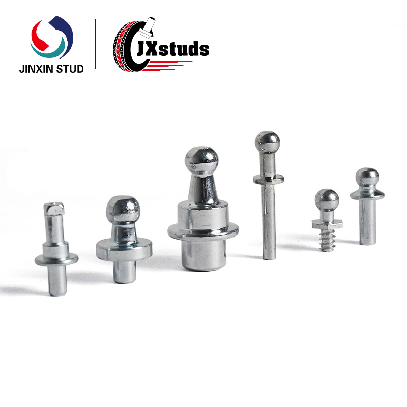
Design Variations
Our product line includes multiple configurations to accommodate different linkage architectures:
| Type | Description | Linkage Function |
|---|---|---|
| Ball Head Screw (Male Thread) | Threaded shank with integral ball head | Attaches to fixed structure; ball engages with external rod end or linkage |
| Ball Head Pin (Unthreaded) | Smooth shank with ball head; retained by clip, cotter pin, or press-fit | Used where threaded attachment is not required or where shear loading predominates |
| Double Ball Joint | Ball heads at both ends | Creates linkage with articulation at both connection points |
| Ball Stud with Shoulder | Ball head with integrated shoulder and threaded shank | Provides positive stop for consistent installation depth |
Precision Manufacturing
Each ball head is manufactured to precise geometric standards that directly influence joint performance:
Sphericity: Deviation from true spherical form maintained within 0.01–0.02 mm to ensure consistent contact patterns
Surface Finish: Ra ≤ 0.4 μm on the spherical surface minimizes friction and wear
Concentricity: Ball center aligned with shank axis within 0.08 mm to prevent eccentric loading
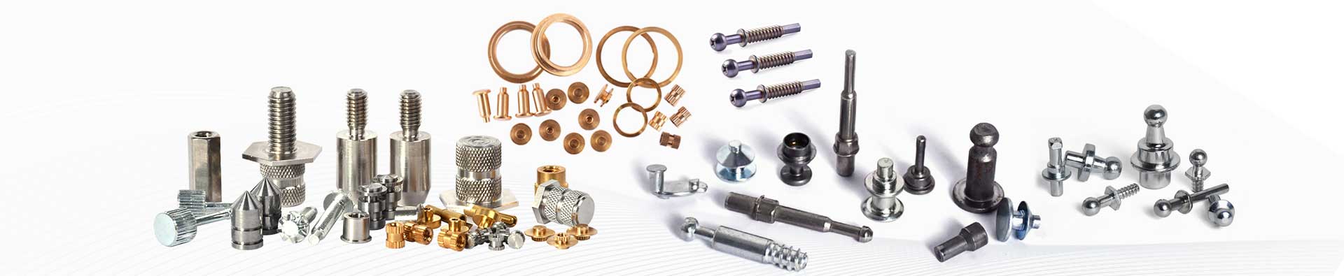
Material & Surface Options
| Material | Properties | Suitability |
|---|---|---|
| Carbon Steel (Grade 8.8 / 10.9 / 12.9) | High strength, heat-treatable, cost-effective | General industrial linkages requiring high load capacity |
| Alloy Steel (4140 / 4340 / 42CrMo) | Superior toughness, fatigue resistance | High-cycle applications, heavy-load linkages |
| Stainless Steel (303 / 304 / 316 / 17-4 PH) | Corrosion resistance, moderate strength | Moisture-exposed or chemically aggressive environments |
| Brass / Bronze | Corrosion resistance, low friction, non-sparking | Specialized environments, bearing applications |
Surface Treatments
Zinc Plating / Zinc-Nickel: Corrosion protection with decorative finish
Black Oxide: Minimal dimensional change, matte appearance
Passivation: For stainless steel, removes free iron and enhances corrosion resistance
Induction Hardening: Localized hardening of ball surface for wear resistance while maintaining core ductility
| Parameter | Standard Range | Notes |
|---|---|---|
| Ball Diameter | 5 mm – 30 mm | Custom sizes available |
| Thread Sizes | M3 – M20, UNF #6 – 3/4″ | Coarse or fine pitch |
| Thread Class | 6g (external), 6H (internal when applicable) | Precision rolled threads |
| Overall Length | 15 mm – 120 mm | Shank length customizable |
| Articulation Angle | 15° – 30° (standard), up to 40° (custom) | Measured from neutral axis |
| Spherical Tolerance | ±0.02 mm – ±0.05 mm | Dependent on diameter |
| Surface Finish (Ball) | Ra ≤ 0.4 μm (standard), Ra ≤ 0.2 μm (precision) | |
| Concentricity | ≤ 0.08 mm | Ball center to shank axis |
| Hardness (Carbon Steel) | 25–45 HRC (core), 50–62 HRC (induction hardened ball) | |
| Tensile Strength | 500–1220 MPa | Dependent on material grade |
| Surface Treatments | Zinc, Zinc-Nickel, Black Oxide, Geomet, Passivation | Custom finishes available |
Articulation Mechanics
The spherical joint operates on principles of conformal contact. When the ball head is seated in its mating socket, the spherical geometry creates a self-aligning interface. As the connected components move, the ball rotates within the socket, maintaining contact across a distributed area rather than a point contact. This distributed contact:
Reduces localized stress concentrations
Distributes wear across the spherical surface
Maintains consistent joint performance throughout the articulation range
Load Path Characteristics
In a typical linkage assembly, forces travel through the following path:
Applied force enters through the threaded shank attachment point
Force transmits through the shank into the ball head
Ball head transfers force across the spherical interface to the socket
Socket distributes force to the linked component
This load path remains continuous regardless of articulation angle, provided the joint remains within its designed angular limits.
Misalignment Compensation
One of the primary mechanical advantages of the ball joint configuration is its ability to accommodate misalignment between connected components. In rigid linkages, manufacturing tolerances, thermal expansion, or assembly variations can create misalignment that induces bending stresses. The ball joint absorbs these angular discrepancies, converting potential bending loads into compressive forces distributed across the spherical interface.
Articulation Torque Management
Articulation torque—the resistance to motion at the joint—is a critical performance parameter. It can be engineered through:
Interference Fit: Controlled clearance between ball and socket creates predictable friction
Surface Finish: Smoother surfaces reduce friction; textured or coated surfaces can increase friction
Lubrication: Integrated or field-applied lubricants modify articulation characteristics
Material Pairing: Ball and socket materials selected for desired friction coefficient
Threaded Shank Installation
For ball head screws with threaded shanks:
Verify thread compatibility with mating tapped hole or nut
Apply appropriate thread lubricant if specified (note that coated threads may incorporate lubricity)
Thread by hand to confirm proper engagement before applying torque
Torque to specified value using wrench on hex flats or socket drive; avoid applying torque directly to the ball head
Verify that the ball head remains unobstructed to allow full articulation range
Press-Fit Shank Installation
For ball head pins designed for press-fit or stud mounting:
Ensure housing hole diameter and surface finish conform to specifications
Clean both shank and housing bore to remove contaminants
Press using appropriate arbor press; maintain perpendicular alignment during insertion
Install retaining clip, cotter pin, or other retention mechanism if required
Verify that the ball head is not deformed by the pressing operation
Socket Mating
Proper mating with the socket component is essential for joint function:
Ensure socket geometry matches ball diameter with appropriate clearance
Verify that socket material and surface finish are compatible with anticipated load and articulation requirements
For applications requiring controlled articulation torque, confirm that socket installation achieves the specified interference or clearance
Each universal ball head fastener undergoes quality verification to ensure consistent mechanical performance:
Dimensional Inspection: Ball diameter, sphericity, concentricity, and thread parameters verified
Mechanical Testing: Tensile strength, hardness, and torque compliance validated per material grade
Surface Verification: Coating thickness, adhesion, and corrosion resistance tested as applicable
Articulation Validation: Sample testing to confirm articulation angle and torque characteristics


")


")
")


")


