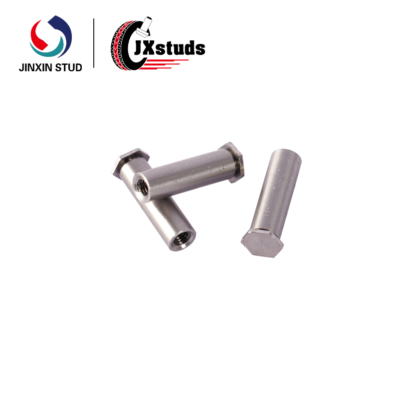
Primary Function & Mechanical Role
The blind hex rivet nut serves three distinct mechanical functions within a single component:
| Function | Description |
|---|---|
| Blind Threaded Receptacle | Provides internal threads that terminate at a closed bottom, preventing through-passage of contaminants, liquids, or foreign objects. The closed-end design also eliminates the need for separate sealing washers or caps. |
| Self-Clinching Mounting | Installs permanently into sheet metal via axial press force. The fastener's knurled or hex-shaped body displaces host material into retention grooves, creating a mechanical lock that resists push-out and torque-out without welding or adhesives. |
| Slotted Head Anti-Rotation | The integrated slot (or broached feature) engages with the panel during installation, providing positive rotational locking. This prevents the fastener from spinning when mating screws are inserted or removed—a critical reliability feature for serviceable assemblies. |
Design Configuration: Blind vs. Through-Hole Standoffs
| Feature | Blind Hex Rivet Nut | Standard Through-Hole Standoff |
|---|---|---|
| Thread Cavity | Closed bottom; sealed termination | Open through-hole |
| Contaminant Protection | Prevents ingress of dust, liquids, debris | No barrier; contaminants may pass through |
| Backside Access | No access required for installation or mating | Backside may require clearance or secondary fastener |
| Sealing Requirement | None; integrated blind design | Often requires separate gasket, sealant, or cap |
| Thread Length | Full thread engagement to closed end | Full through-thread or partial depth |

Installation Method
Installation follows a straightforward press-in process suitable for manual, pneumatic, or automated equipment:
| Step | Description |
|---|---|
| 1. Hole Preparation | Punch or drill mounting hole to specified diameter (typically +0.05/-0.00 mm). Deburr to ensure clean edges for uniform material flow. |
| 2. Fastener Placement | Insert blind hex rivet nut into the mounting hole from the accessible side. The slotted head aligns with the panel surface; the blind end projects into the cavity behind. |
| 3. Pressing | Apply axial force using arbor press, pneumatic press, or servo-driven equipment. Force requirements range from 10 kN to 50 kN depending on fastener size and panel thickness. |
| 4. Material Flow | Displaced sheet metal flows into the fastener's retention grooves, creating a permanent mechanical lock. The slotted head embeds into the panel surface, establishing anti-rotation features. |
| 5. Verification | Inspect for flush seating (head should be level with or slightly below panel surface). No secondary operations required. |
Key Installation Advantages:
Single-Side Access: Installation performed entirely from one side of the panel; no access required to the opposite side
No Welding: Eliminates heat distortion, spatter, and post-weld finishing
No Secondary Sealing: Blind design eliminates need for separate sealing components
Automation Ready: Compatible with standard insertion equipment; tape-and-reel packaging available for high-volume lines
Primary Application Domains
The blind hex rivet nut is specified across industries where sealed threaded connections in sheet metal are required, particularly where backside access is restricted:
| Application Area | Specific Use Cases | Rationale |
|---|---|---|
| Electrical Enclosures & Control Panels | Sealed mounting points for circuit boards, terminal blocks, DIN rail components, and internal brackets | Blind design prevents dust and moisture ingress through fastener openings, maintaining enclosure IP rating (IP54–IP66). Single-side installation accommodates pre-assembled enclosures where backside access is blocked by internal components. |
| Automotive Electronics | ECU (engine control unit) mounting, sensor housings, battery management system enclosures | Vibration resistance critical; slotted head prevents loosening. Blind termination protects sensitive electronics from moisture and road contaminants. |
| Medical Devices | Diagnostic equipment housings, patient monitoring systems, surgical instrument enclosures | Sealed threads prevent fluid ingress during cleaning and disinfection. Stainless steel construction meets sterilization compatibility requirements. |
| Telecommunications Infrastructure | Base station enclosures, antenna mounting plates, RF shielding assemblies | Outdoor deployment demands sealed fasteners to prevent corrosion and moisture damage. Blind configuration eliminates need for field-applied sealants. |
| Aerospace & Defense | Avionics chassis, radar enclosures, portable military electronics | High-reliability threaded connections in space-constrained assemblies. Blind design prevents foreign object debris (FOD) entry. |
| Food Processing Equipment | Stainless steel control boxes, sensor mounting points, washdown enclosures | Sealed threads prevent bacterial harborage. Stainless steel A4 (316) construction provides corrosion resistance to cleaning chemicals and high-pressure washdowns. |
Material & Configuration Options
| Parameter | Specification |
|---|---|
| Material | Stainless Steel A2 (304) – standard; A4 (316) – marine/chemical grade |
| Thread Sizes | Metric: M3 – M10; Inch: #4-40 – 3/8″-16 |
| Overall Length | 8 mm – 25 mm (custom lengths available) |
| Panel Thickness Range | 0.8 mm – 3.5 mm |
| Head Style | Slotted, flush, or low-profile |
| Body Profile | Hexagonal or round with knurl |
| Finish | Passivated (standard); electropolished optional |
| Parameter | M4 x 12 mm | M5 x 15 mm | M6 x 18 mm | #8-32 x 1/2″ |
|---|---|---|---|---|
| Thread Size | M4 × 0.7 | M5 × 0.8 | M6 × 1.0 | #8-32 UNC |
| Overall Length (L) | 12.0 mm | 15.0 mm | 18.0 mm | 12.7 mm (0.5″) |
| Hex Body Width (AF) | 6.0 mm | 8.0 mm | 10.0 mm | 0.312″ (7.9 mm) |
| Head Diameter | 8.0 mm | 10.0 mm | 12.0 mm | 0.375″ (9.5 mm) |
| Head Height | 1.5 mm | 1.8 mm | 2.0 mm | 0.060″ (1.5 mm) |
| Blind Depth (Internal) | 8.0 mm | 10.0 mm | 12.0 mm | 8.0 mm |
| Recommended Panel Thickness | 1.0 – 2.0 mm | 1.2 – 2.5 mm | 1.5 – 3.0 mm | 1.0 – 2.0 mm |
| Mounting Hole Diameter | 5.6 ±0.05 mm | 7.2 ±0.05 mm | 9.0 ±0.05 mm | 0.281″ ±0.002″ |
| Installation Force (kN) | 12 – 18 | 18 – 25 | 25 – 35 | 15 – 22 |
| Push-Out Resistance (N) | 450 | 650 | 900 | 500 |
| Torque-Out Resistance (N·m) | 4.5 | 7.0 | 11.0 | 5.5 |
| Parameter | A2 Stainless (304) | A4 Stainless (316) |
|---|---|---|
| Tensile Strength (MPa) | 500 – 700 | 500 – 700 |
| Hardness (HRB) | 80 – 95 | 80 – 95 |
| Corrosion Resistance (Salt Spray) | 500+ hours (passivated) | 1,000+ hours (passivated) |
| Operating Temperature Range | -40°C to +300°C | -40°C to +400°C |
| Magnetic Properties | Non-magnetic (slightly magnetic after cold working) | Non-magnetic |
| RoHS / REACH | Compliant | Compliant |
| Typical Applications | General industrial, electronics, medical | Marine, food processing, chemical exposure |
| Quality Aspect | Description |
|---|---|
| Thread Verification | 100% go/no-go gauging on internal threads; Class 6H (metric) / 2B (inch) conformance |
| Dimensional Inspection | CMM and optical comparator sampling; critical dimensions documented per batch |
| Installation Validation | Periodic push-out and torque-out testing per ASTM standards |
| Material Traceability | Full lot traceability with Material Test Reports (EN 10204 3.1) |
| Packaging | Bulk cartons with anti-corrosion protection; tape-and-reel available for automated insertion |
| Custom Feature | Options |
|---|---|
| Thread Size | Metric M2 – M12; Inch #2 – 1/2″; special pitches available |
| Length | 6 mm – 35 mm; any custom increment |
| Head Configuration | Slotted (standard), flush, countersunk, or low-profile |
| Body Profile | Hexagonal (standard), round with knurl, or custom geometry |
| Material | A2 (304), A4 (316), 17-4 PH stainless; carbon steel with plating available |
| Finish | Passivated, electropolished, bead blasted |
| Thread Locking | Pre-applied nylon patch for vibration resistance |
| Blind Depth | Custom blind depth to accommodate specific screw lengths |


")


")
")


")


